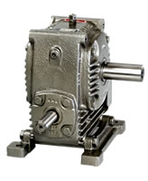
B.R reduction gearboxes casing are built sturdily with close grained, Cast Iron conforming FG 260 grade. The gearbox is provided with amply designed fins with suitable fan for adequate dissipation of heat generated. The entire design is based mainly on BS 721 / 1963 to accuracy class A. BIS Specifications are used wherever possible. The gearbox design is in such way that is interchangeable with the standard gearboxes.
The worm is of high quality casehardening steel very accurately generated and ground finished for the better performance. The worm wheel is of extremely high quality phosphor bronze spin cast with a considerably substantial section, rigidly held to a strong hub with eutectic welding technology / Sandwich Casting.
Both worm and worm wheel shafts are mounted on quality tapered roller / angular contact bearings with adequate safety margin to handle the over-hung loads. Subject to the limitation of oil temperature of 90°C under full load, the gearbox will give a minimum gear life of 20,000 hrs. Lubrication is positive. B.R Gearboxes require absolutely no attention at all in operation, excepting for the oil level check once in fortnight.
Lubrication:
Recommended Lubricant ISO VG 320 I SERVO SYSTEM 320
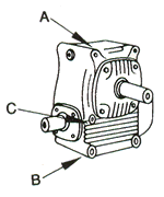
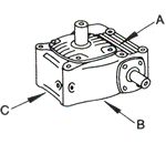
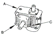
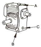
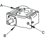
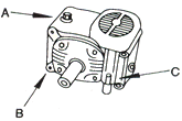
The B.R Speed Reducer lubrication system is self contained positive and automatic at all speeds of operation and in either direction of rotation. Adaptable units are provided with breather, oil level and drain plugs and it must be ensured that these are correctly positioned as shown on the accompanying diagram. Other units incorporate a dipstick for oil level checking, an oil filler-cum-ventilator, and drain plugs. Their locations are shown below.
B.R Speed Reducer units are supplied without oil and must be filled with the correct grade of lubricant to the correct level. It is important to ensure that the correct oil level is not exceeded as over filling causes oil churning which results in overheating and leakage.
| A – Oil filler-breather | B – Oil Drain | C – Oil Level | D – Grease Point |
| Position – A | Position – B | Position – C |
 |  |  |
| |
| Position – D | Position – E | Position – F |
 |  |  |
Installation and Maintenance
Installation
Gearboxes are to be rigidly mounted so as to minimize the effect of fluctuating or heavy loads. Always check the alignment after bolting down. After installation and alignment has taken place, properly locate the gear unit by means of dowels at appropriate locations preferably in diagonal direction.
The use of flexible couplings (Love joy / Gear coupling flanges with rubber bushes/tyre couplings) is very important for the improved performance of the gearbox. The couplings are to be lined up to avoid the misalignment of angularity and eccentricity.
Change of Handing
When changing the handing of the slow shaft extension, the shaft complete with worm wheel, bearings etc. should be reversed as a unit. It should be appreciated that this has the effect of reversing the offset of the wheel relative to the worm. When changing the slow speed shaft handing of V type units, it should be noted that the position of the wheel relative to the case must not be changed; it is necessary therefore to press the wheel from the shaft. The position of the shaft in relation to the worm wheel must be reversed. The end covers should be located in their respective positions.
It is necessary to check contact markings on the worm wheel teeth and if any axial adjustment of the worm wheel is necessary, it can be effected by means of the shims between covers and bearing housing, which should be moved from one side to the other. It is essential that the top half of the gear case be replaced in its original position (Not applicable for Adaptables).
The contact marking is checked by painting the worm with red lead of Prussian Blue and rotating the worm by hand while applying a small breaking pressure to the wheel by hand. The correct marking should be slightly heavier on the “leaving side” of the teeth, relative to the direction of rotation of the worm, so as to provide “lead in” for the lubricant and to avoid concentration of pressure on the entering side as this would affect the smoothness of operation.
Axial Floats
After re-handing it is essential that shaft and floats be correctly set. The following axial floats for wormshaft and wheelshaft are recommended. They should be checked preferably using a dial
| Size | Wormshaft (mm) | Wheelshaft (mm) |
| 112 | 0.050/0.100 | 0.025/0.050 |
| 162 | 0.050/0.100 | 0.025/0.050 |
| 200 | 0.050/0.100 | 0.025/0.050 |
| 237 | 0.050/0.100 | 0.025/0.050 |
| 287 | 0.050/0.100 | 0.025/0.050 |
| 337 | 0.050/0.100 | 0.025/0.050 |
Weekly Inspection
 | Check the oil level by means of the dipstick or oil level plug and add the recommended lubricant to the level if required |
 | Ensure that breathers are clean and operating properly, if blocked clean the breathing holes otherwise pressure will build up, resulting in oil leakage |
 | Units fitted with grease nipples, add two or three shots of grease from grease gun |
 | Regular oil changes are essential to ensure that the unit gives long and trouble free service, which depends upon the following factors |
 | Oil temperature- under load |
 | Environment- humidity, dust etc |
 | Operating conditions- shock loading etc |
 | Replace the oil as per operating conditions at elevated temperatures- Refer below |
| Temperature | Adaptables | Other Units |
| 75 or Less | 2500 hrs or 6 Months | 5000 hrs or 12 months |
| 80 | 2000 hrs or 6 Months | 3500 hrs or 12 months |
| 90 | 1000 hrs or 3 Months | 1000 hrs or 12 months |

